Zero Potential
The thin layer of material which covers our planet – rock, clay, chalk or whatever – is what we in the world of electricity refer to as earth. So, why do we need to connect anything to it? After all, it is not as if earth is a good conductor.
It might be wise at this stage to investigate potential difference (PD). A PD is exactly what it says it is: a difference in potential (volts). In this way, two conductors having PDs of, say, 20 and 26 V have a PD between them of 26 and 20V. The original PDs (i.e. 20 and 26 V) are the PDs between 20 V and 0 V and 26 V and 0 V.
So where does this 0 V or zero potential come from?The simple answer is, in our case – the earth. The definition of earth is, therefore, the conductive mass of earth, whose electric potential at any point is conventionally taken as zero.
Thus, if we connect a voltmeter between a live part (e.g. the line conductor of a socket outlet) and earth, we may read 230 V; the conductor is at 230 V and the earth at zero. The earth provides a path to complete the circuit. We would measure nothing at all if we connected our voltmeter between, say, the positive 12 V terminal of a car battery and earth, as in this case the earth plays no part in any circuit.
Figure 1 illustrates this difference.

So, a person in an installation touching a live part whilst standing on the earth would take the place of the voltmeter and could suffer a severe electric shock. Remember that the accepted lethal level of shock current passing through a person is only 50 mA or 1/20 A. The same situation would arise if the person were touching a faulty appliance and a gas or water pipe (Figure 2).

One method of providing some measure of protection against these effects is, as we have seen, to join together (bond) all metallic parts and connect them to earth. This ensures that all metalwork in a healthy installation is at or near 0 V and, under fault conditions, all metalwork will rise to a similar potential.
So, simultaneous contact with two such metal parts would not result in a dangerous shock, as there would be no significant PD between them. Unfortunately, as mentioned, earth itself is not a good conductor, unless it is very wet. Therefore, it presents a high resistance to the flow of fault current. This resistance is usually enough to restrict fault current to a level well below that of the rating of the protective device, leaving a faulty circuit uninterrupted.
Clearly this is an unhealthy situation.
In all but the most rural areas, consumers can connect to a metallic earth return conductor, which is ultimately connected to the earthed neutral of the supply. This, of course, presents a low resistance path for fault currents to operate the protection.
In summary, connecting metalwork to earth places that metal at or near zero potential and bonding between metallic parts puts such parts at a similar potential even under fault conditions. Add to this a low-resistance earth fault return path, which will enable the circuit protection to operate very fast, and we have significantly reduced the risk of electric shock.
Earth fault loop impedance
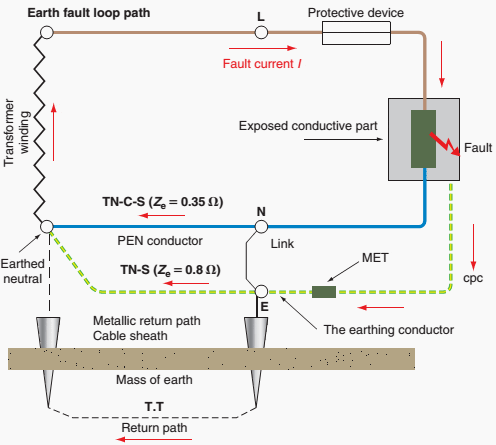
As we have just seen, circuit protection should operate in the event of a fault to earth. The speed of operation of the protective device is of extreme importance and will depend on the impedance of the earth fault loop path.
Figure 3 shows this path. Starting at the point of the fault, the path comprises:
- The circuit protective conductor (cpc)
- The consumer ’s earthing terminal and earthing conductor
- The return path, either metallic or earth itself
- The earthed neutral of the supply transformer
- The transformer winding
- The line conductor from the transformer to the fault.

Figure 4 is a simplified version of the loop path.

From Figure 4 , we can see that the total earth fault loop impedance (Zs) is made up of the impedance external to the installation (Ze), the resistance of the circuit line conductor (R1) and that of the circuit cpc (R2), i.e.
Zs = Ze + R1 + R2
we also have, from Ohm’s law, the value of the fault current that would flow from
I = U0 / Zs
where U0 is the nominal voltage to earth (230V).